Car Park Ventilation Regulations
Car Park Ventilation is essential to preventing the build-up of toxic fumes and flammable gases from motor exhausts as well as clearing smoke in the event of a fire. The Building Regulations specify what is required to maintain safe conditions, in particular, Approved Document B for ventilation of smoke from a fire, and Approved Document F for ventilation of vehicle exhaust gases. Natural Car Park Ventilation is the preferred method of ventilating car parks, as it simply requires openings to fresh air being provided with a free area equal to a percentage of the floor area of the car park. The areas to be provided are currently:
- 5% for ventilation of everyday vehicle pollution and smoke with at least 50% being provided between opposite faces of the building; the openings provided must be sufficient to create a through draught.
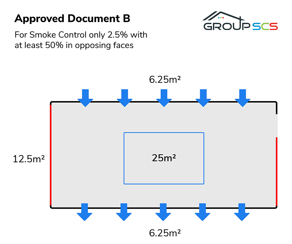
- 2.5% for smoke clearance only with at least 50% being provided in opposite faces of the building. This is not in addition to the 5% for pollution control so if you can achieve 5% then that is sufficient for both purposes.
Method of calculation
For an area suitable for both smoke control and pollution ventilation.
Step 1: Calculate the floor area of the car park
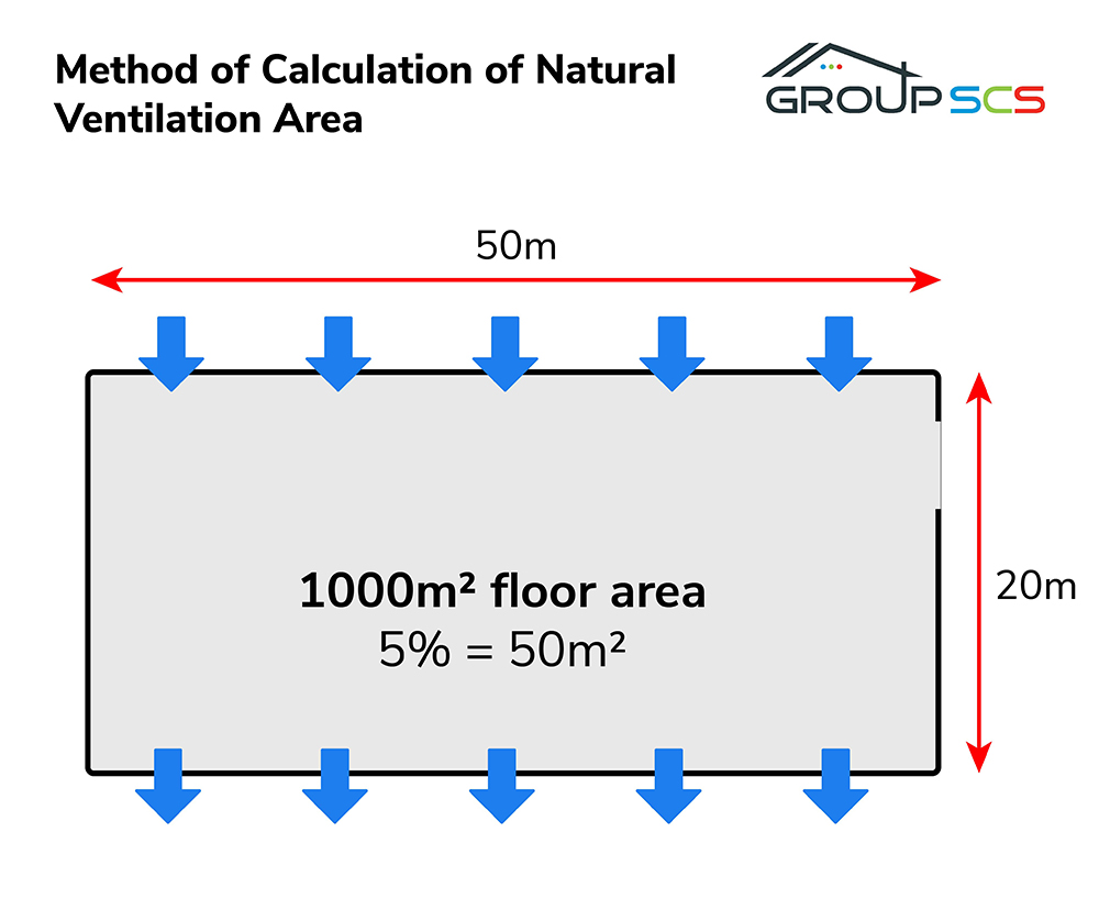
Step 2: Calculate 5% of the floor area
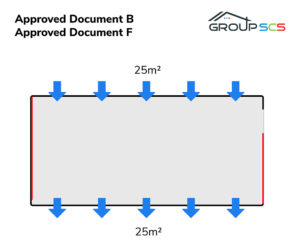
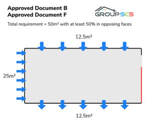
Step 3: Position the ventilation openings to ensure crossflow as illustrated
It is possible to provide a hybrid solution where only 2.5% for smoke control can be provided naturally and this is then supplemented by a mechanical CO ventilation system to limit the concentration of CO within the space.
If the natural ventilation for smoke control is achieved then an automatic pollution ventilation system utilising jet fans and a CO sensing control system is a cost-effective solution.
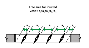
The free area of a louvre is defined in appendix D of Approved Document B as the total unobstructed cross-sectional area (geometric free area), measured in the plane where the area is at a minimum and at right angles to the direction of airflow (Diagram D7).