In this article, we’ll take a look at some practical recommendations for implementing smoke shaft systems in multi-storey buildings. As a start, we will provide a bit of background and history on smoke shafts and the standards that apply to their implementation. Following this, we will examine the use of smoke shaft dampers and the current guidance that surrounds them and offer our recommendations.
What is a smoke shaft used for?
Commonly known as ‘smoke shafts’, ventilation systems in the lobbies of tall buildings are used to maintain tenable conditions in the common escape routes in the event of a fire in the building.
Smoke shafts originated from research carried out by BRE and presented in a report in 2002, titled ‘Smoke Shafts Protecting Fire Fighting Shafts, Their Performance and Design’. This report specifically looked at fire-fighting shafts and proposed natural ventilation – with the output being commonly known as the ‘BRE Shaft’.
The natural desire to reduce the space occupied by the ventilation system has led to new developments in smoke shafts. Due to their potential to save space, mechanically ventilated shafts grew in popularity for both firefighting and means of escape. Nowadays, such systems are routinely used to justify escape travel distances in excess of those recommended in Approved Document B of the Building Regulations (ADB). This is done on the basis that they offer a higher standard of protection than that provided by natural ventilation.
Smoke shaft dampers
The extract point from the lobby into the smoke shaft is fitted with a damper of the required free area and resistance to permit the evacuation of the quantity of air/smoke specified in the system design for mechanical systems, or to give the specified free area in natural shaft systems.
The damper on the fire floor is required to open to ventilate the lobby, while all dampers on other floors must remain closed to prevent smoke spreading between floors. In the absence of a British or European standard for the application, a number of ad hoc products have been used as smoke shaft dampers including:
- Fitting an actuator to a fire door
- Using a fire damper with the fusible link removed and a motor added
The suitability of these solutions would rely on the knowledge and experience of the specifier and the vendor and whilst they may be appropriate for the purpose, the task of assessing and validating such products is difficult without a common test regime.
Current Guidance on smoke shaft dampers
As of now, there is still no specific british standard or test for the application and a what advice there is can be conflicting, confusing and open to interpretation.
ADB offers guidance for natural smoke shaft dampers as follows:
Paragraph 3.51iii
All vents (serving a natural smoke shaft) should either be a fire door set (see Appendix C, Table C1, item 2.e for minimum fire resistance), or fitted with a fire and smoke damper (see paragraph 9.21).
Paragraph 9.21
Fire and smoke dampers should meet both of the following conditions:
- Conform to BS EN 15650.
- Have a minimum ES classification of 60 minutes or to match the integrity rating of the fire resisting elements, whichever is higher.
It is impossible to comply with the conditions specified above as dampers to BS EN 15650 are fitted with a thermal device to automatically close the damper. In a smoke shaft application, the damper on the fire floor is needed to open and such a thermal device could lead to the damper closing and the system failing.
BS 9991:2015 Fire safety in the design, management and use of residential buildings
Code of practice
14.2.3.2 Natural smoke shafts situated above ground level
- The lobby or corridor vent, the opening at the head of the shaft and all internal locations (such as safety grilles) within the shaft should have a free area of at least 1.0 m2.
- The top of the lobby or corridor vent should be located as close to the ceiling of the lobby or corridor as is practicable and should be at least as high as the top of the door connecting the lobby or corridor to the stairwell.
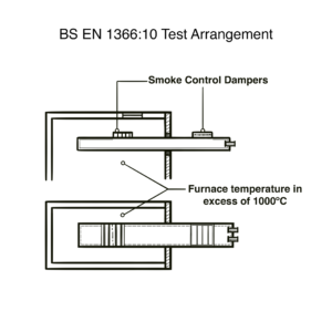
- The lobby or corridor vents, in the closed position, should have a minimum fire and smoke resistance performance of 30 min and integrity (leakage) no greater than 360 m3/h/m2 when tested in accordance with BS EN 1366-2
BS EN 1366-2 is the test standard for fire dampers, smoke control dampers are tested to 1366-10
SCA ‘Guidance on Smoke Control to Common Escape Routes in Apartment Buildings (Flats and Maisonettes)’
The Smoke Control Association produces the most comprehensive guidance on this subject in the Guidance on Smoke Control to Common Escape Routes in Apartment Buildings which was revised in January 2020. Paragraph 8.2.2 Smoke Control Dampers recommends the use of smoke control dampers meeting the requirements of BS EN 12101-8 and advises against the use of fire doors and fire dampers certified to BS EN 15650 and adhoc products tested to BS EN 12101-2.
Excerpt from the SCA Guide
8.2.2 Smoke control dampers
Smoke control dampers are used where there is a need to control the extract of smoke from within a building, for example between a lobby or corridor and a smoke extract shaft or duct, or ducting air directly to the outside of a building. The system designer must select the appropriate product in conjunction with building control and the fire brigade.
Smoke control dampers should be selected to reflect requirements of the smoke control system and accommodate the maximum performance requirements of the system (sizes, volumes and pressures)
For example, smoke control dampers mounting in walls to allow access to shafts which will breach vertical compartmentation shall be multi compartment smoke control dampers.
Products should be CE marked to BS EN 12101 Part 8.
ADB requires the use of smoke control dampers in association with smoke controlThe smoke control damper selected should have an integrity value to suit the compartment barrier or ductwork into which it is to be installed
The use of fire doors with actuators is allowed under ADB but is not a solution recognised by the SCA, as products meeting the requirements of the EN12101 series is advocated.
Other ad hoc tested products or products meeting the requirements of EN 12101-2 are not allowed for allowing smoke to enter a vertical shaft and are not allowed under ADB.
Similarly, the use of fire dampers CE marked to EN 15650 with replaced actuators is not acceptable as the smoke control damper test requires the actuator to be cycled before the fire tests and to be part of the tested smoke control damper assembly.
(NOTE: DW/144 Section 24 advises use of fire damper CE marked to EN 15650 then modified for use in smoke control. This is no longer acceptable as the CE mark is invalid for use as smoke control damper, which has its own CE marking requirements.)
BS EN 12101-8 Was not developed for smoke shaft dampers
The decision to recommend smoke control dampers for this application was made from a desire to have products tested to a recognised standard to improve consistency and ensure the quality of the installed product. As previously stated, there is no specific test that replicates the smoke shaft damper situation and there are significant differences in practice from the typical smoke control damper application and the fire test conditions required for certification to BE EN12101-8 are far more stringent than those likely to be experienced in reality.
EN12101 Part 8: Smoke control dampers
This standard is the closest fit to the smoke shaft damper application. However, this particular application does not replicate the typical smoke control damper situation to precision. The closest approximation would be the smoke control damper for a multi-compartment, as item 10 in figure 1 of BS EN 12101-8.
There are, however, significant differences in the smoke shaft application, in particular:
- Unlike a typical mechanical smoke extract system, a smoke shaft, is located remotely from the fire zone. In a typical residential building, the smoke shaft is in the lobby is separated by the apartment compartmentation from the typical bedroom or kitchen fire zone.
- The test apparatus for a smoke control damper places the damper directly in the furnace resulting in a much higher temperature than that typically experienced in a smoke shaft situation.
- The extract fans will be operating to maintain a constant negative pressure within the shaft preventing leakage from closed dampers.
A detailed look at significant distinctions
The remoteness of the damper from the fire compartment results in far lower temperatures than a damper in a typical building services air movement application may experience. The damper on the fire floor will be open to allow for smoke evacuation and dampers above will stay closed to prevent smoke leakage between floors. From modelling data, the typical maximum temperatures within the shaft would be ≤100⁰C as illustrated in Appendix 1.
The damper will be under negative pressure either from the buoyancy of the smoke in a BRE shaft or due to the action of the extract fans in a mechanical extract shaft.
This negative pressure will prevent the smoke from escaping from the shaft in upper floors providing the system has been designed to handle the leakage characteristics of the damper and the shaft has been correctly constructed This situation can be likened to that of a pressurisation system in accordance with EN12101:6 – Smoke and Heat Control Systems, Specification for pressure differential systems.
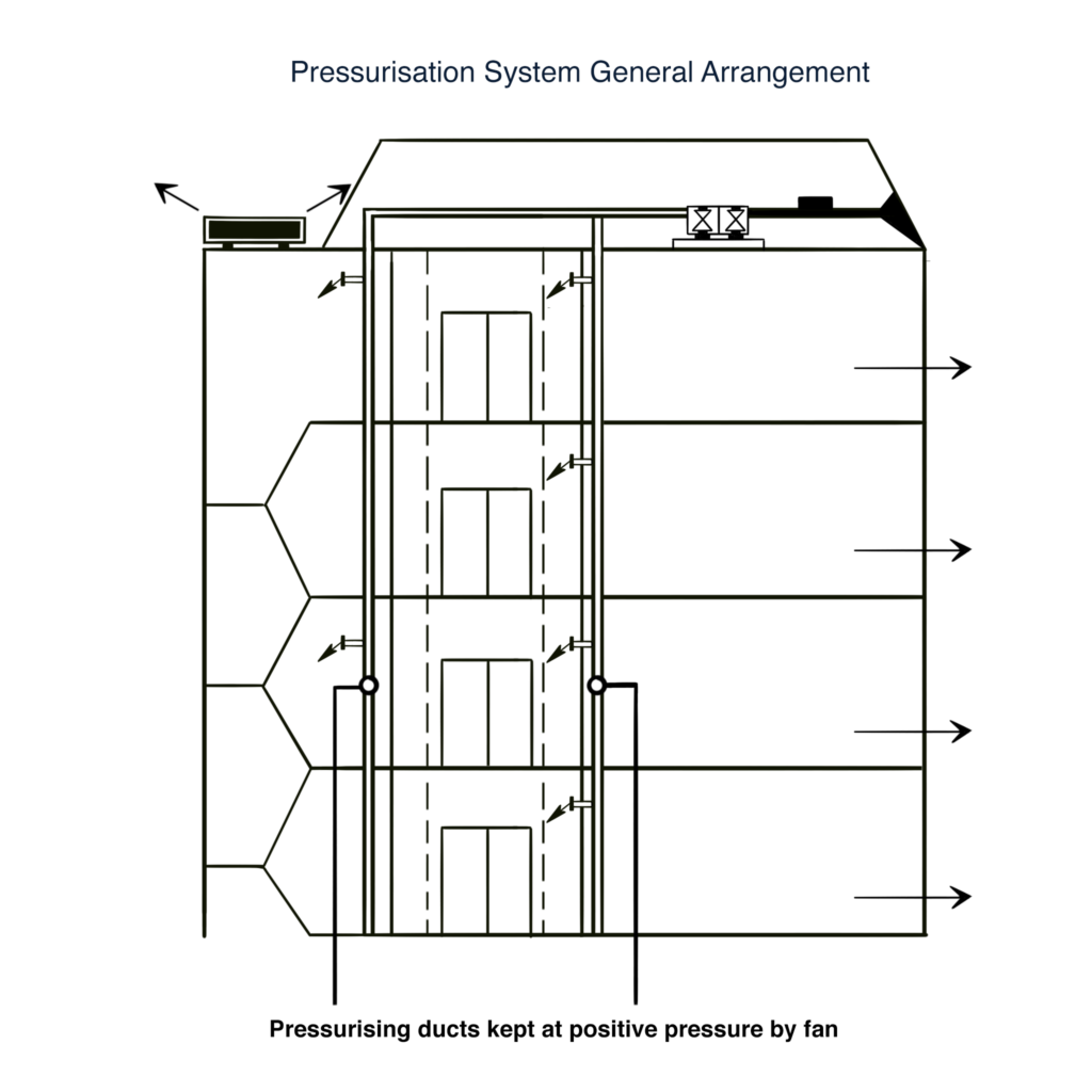
Looking at the delivery duct for the pressurising air to the lobby, it can be seen that there is no smoke control damper required to prevent smoke travelling between floors. This is due to the duct being under positive pressure from the action of the delivery fan. Relevant safeguards are in place to ensure the continuing operation of the fan e.g. run and standby fans, and back-up power supplies and these are deemed sufficient to negate the need for smoke control dampers. In a correctly designed mechanical extract shaft system, these same safeguards will be in place ensuring that smoke cannot migrate between floors (see Appendix 2).
A note on Natural shafts in high rise applications
As stated above, smoke shafts are generally maintained at a negative pressure in a fire scenario, either due to fan pressure or from the natural buoyancy of the hot exhaust gasses. However, in tall buildings, the smoke in a natural smoke shaft may cool as it goes up the shaft to roof level. Smoke cooling within the uppers floors of a tall shaft may cause areas of local positive pressure, which may lead to smoke leakage out of the shaft into non-fire affected floor levels. It is recommended that natural smoke shaft dampers have S classification.
Recommendations
Taking the above factors into account, we look at the characteristics contained within 12101:8 and arrive at recommended minimum standards for natural and mechanical smoke shafts.
Minimum (*) – E60 (Vex and/or Hox) 1000 AA i→0 C10000 multi (for the value of x – see the table)